First continuous frequency coverage presenting a low VSWR to your transceiver. It is a simple matter of making some adjustments to ensure the best match on each band.
2
The Ten-Tec Model 3402 Broadband Terminated Vee Beam Antenna offers continuous coverage between 18 and 30 MHz with a maximum VSWR of 21typically 141 or less.

. The Vee Beam Antenna. 137 - Wire Beam 6dBd-Gain for 10m. 136 - Bi-Loop Antenna for 20m.
An important factor to keep. Build Them and the DX will Come. By the definition the sloping terminated vee-beam has a similarity to the dipole.
Symmetrical Vee antenna having a specified arm length can have maximum directivity for an optimum Vee angle 16. Layout of the Vee Beam The two key parameters of a Vee Beam are the leg length Πthe length of each wire measured from the feed-point Πand the included angle Πthat is the angle that the two wires legs make to each other. REF2 Horizontal V Antenna for 15 Meters The HORIZONTAL V ANTENNA FOR 15 METERS This often leds to the question of what is a Beam Antenna.
Each Rhombic antenna uses over 12 Mile of 38 cable. 138 - Sloping Diamond Antenna 4dB-Gain for 40m. The design described here was in use for several years proved to be highly reliable and generally capable of outperforming a tribander on 20 15 and 10 for stations in the Vee beamss line of fire.
90 degrees and gain is about 25 dbd with a bidirectional pattern along the line bisecting the legs. Fencing wire with the ends spaced 170 feet apart. Other multiband wire dipole antennas will require the use of an antenna tuner on one or more HF bands - Ten-Tecs broadband vee-beam does not.
Antenna Design Vee dipoles are characterized by increase in directivity and reduced sidelobes as compared to their linear counterparts. In it smallest of states the Horizontal Vee must be one of the least researched or understood antennas. 139 - Twisted Loop Antenna for 160m.
Array Solutions Terminated Vee Beam Phn. Inverted V 3 element at 11m green Horizontal dipole at 16m red 58λ top loaded on 18m high fiberglass mast 32 radials 20m long pink. With 1 wavelength legs the angle between the legs is ideally approx.
They are erected on 100 foot wooden utility poles also the site has two large Vee Beam antennas which are over 1200 foot long each. For both models VHF. Harper of Bell Labs W6AM Don Wallaces antenna farm a traveling-wave VOA BBC.
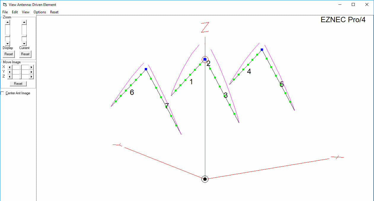
The angle formed between the two sloping wire elements at the apex point is an antenna design parameter that is designated as the Apex Angle. Vee beams Ive field tested showed little or no noticeable gain or directivity until the leg lengths were at least 1 wavelength. Figure 1 Sloping Vee Configuration.
HF shortwave point to point and broadcast broadband directional antenna diamond antenna. Each leg is 300 feet in length. The proposed multi-beam antenna is composed of four.
One might note that a standard dipole is actually a special case where the Apex Angle is 180. The third antenna is a 10-meter Vee-beam. 140 - DX RX Loop Antenna for 160m.
A Vee Beam will perform well as a directional antenna with a leg length of between 1 and 5 wavelengths. The antenna is set up with an angle greater than 120 degrees at the apex to get the impedance match about right. Ireland is very well located as you are able to reach 75 of the radio traffic with an opposite antenna direction therefore I decided to make a bi-directional antenna design.
The open ends point in the desired signal direction on the premise that we shall get added gain from them. My 1 wave 20m vee beam with the feedpoint at. The dimensions of this antenna were provided by Nick VE3OWV.
ARRL RSGB Diamond Logo Rhombic Antenna Vee Beam V Rhombic antenna Ed Bruce and Harald Friis. 141 - Hentenna 3dB-Gain for 10m. 135 - Collinear Vertical Antenna 6dB-Gain for 2m 13m 73cm.
Dipole 1-λ loop or Inverted Vee yields about 1 dB gain It has a negligible effect on the antennas bandwidth It requires appx. 133 - Collinear Zepp Antenna. The Model 3403 is a shorter version of the antenna that covers 35 to 30 MHz with a maximum VSWR of 21typically 141 or less.
134 - Taylor Vee Antenna for 20m. The Vee Beam Antenna. The Ten-Tec broadband vee-beam offers a number of advantages over a typical flat-top multiband dipole or windom.
Each element has a quadrant form that is a 90-degree overall bend. 2800 feet of wire for 80m or 1476 feet for 40m It requires a space of 311 ft x 207 ft for 80m or 164 ft x 109 ft for 40m. If youre lucky enough to have the room perhaps you may like to put up a multiband Vee Beam antenna for the HF bands.
The vee- beam can be viewed as an inverted dipole antenna fed in the center like a dipole. The dimensions are not critical. The antenna used at VE3OWV is shown in Figure 1.
A diagram of a typical half-wave resonant center-fed dipole Inverted V antenna. The center is elevated as high as possible from ground surface however the ends slope to close to the surface. Rhombic Antenna Design AE.
I determined the antenna length by using the usual dipole formula less 5 because of the inverted Vee configuration. Angle a can be almost anything provided.
Rhombic Antennas V Beam And Inverted V

Vee Beam K5nd
Rhombic Antennas V Beam And Inverted V

Yf1ar Yankee Foxtrot One Alpha Romeo The Vee Beam Antenna

The Persistent Vee Beam Myth

3 Half Wave Horizontal Vee Beam Ham Antenna Project

The Kb4xj One Element V Beam The Vee Beam 15 Meter Project
A High Performance 40m Antenna Optimization For Field Day
0 comments
Post a Comment